
Clinical damage analysis of dental materials for better long-term success
In the past ten years, dentists and dental technicians have experienced a multitude of innovations, and they are now confronted with an enormous diversity of materials and variants. This brings an ever increasing complexity to everyday work in dental practice and laboratory life, since very different manufacturers’ specifications for processing must be observed for many materials or material variants. This increasing complexity can also increase the risk of error in the technical and clinical application. In the following interview, dental technician and dental technologist Kathleen Kaufman reports on how she can detect common causes of chipping or fracture using clinical fractography analysis. The goal is to develop recommendations for error prevention to enable long-term clinical success.
DV: What is the procedure for clinical damage analysis and what procedures are used?
Kathleen Kaufman: In damage analysis, defective restorations are examined by means of different methods in order to determine the cause of failure. Frequently, a scanning electron microscope (SEM) is used for this purpose. With this microscope, for example, we can analyze fracture surfaces of fractured restorations with up to 100,000x magnification. At this magnification, conclusions about the cause of the material failure can be derived from the type and structure of the fracture surface. On the basis of these findings, concrete recommendations for safe processing can then be created.
DV: How can fracture or chipping risks alreadybe minimized during the planning and design of restorations?
Kathleen Kaufman: Material failure or chipping can actually have its origin in the planning or design phase. In the SEM analysis of veneered zirconia restorations, it has been shown, for example, that ceramic spalling is often due to a lack of framework support for the veneer. Here, it is advisable to design the framework as anatomically as possible so that uniform coverage can always be achieved during veneering. Falling short of minimum wall thicknesses, insufficiently large connector cross-sections, and incorrectly dimensioned connectors are further parameters that increase the risk of fracture.
DV: What findings does damage analysis offer for the safe and material-appropriate processing of zirconia?
Kathleen Kaufman: The fracture of zirconia substructures is often caused by punctiform machining with worn diamond grinding wheels or with the separating wheel. When performing damage analysis with SEM, it can be seen that crack propagation often originates from these sites, which leads to material failure. In general, frameworks should always be finished before sintering and never on the connector itself. In addition, take care to maintain a low speed and a low contact pressure to prevent overheating. Finally, the framework should be designed so that it has no sharp corners and edges, as this can lead to tensions in the veneering ceramic.
DV: What potential sources of failure did you discover in your glass ceramic firing studies?
Kathleen Kaufman: For glass-ceramic restorations, it has been shown that strict adherence to the manufacturer’s specifications for crystallization is important in order to avoid defects. For example, if a restoration is crystallized directly on a ceramic pin, the firing pin may adhere to the crown. If the crown is removed from the firing pin and support after firing, this can cause micro-cracks. By using firing paste or platinum pins, however, such material damage can be avoided.
DV: What potential risk factors could you identify in the clinical use of ceramic materials in dental practices?
Kathleen Kaufman: During the try-in, the restoration is often ground again. Here, it is imperative to polish, or, better, to re-glaze the processed surfaces. Investigations show that micro-cracks are often introduced into the material by manual processing with diamond-coated instruments. The chewing load and moisture in the oral cavity can lead to further crack growth, up to partial or complete restoration failure.
Report 07/19
Kathleen Kaufman, Bad Säckingen, Germany
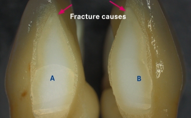
Fig. 1a: The framework was separated between 31 and 41 for esthetic reasons after sintering.
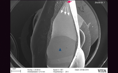
Fig. 1b: Crack formation, which eventually led to the fracture, started from the incisally damaged framework structure.
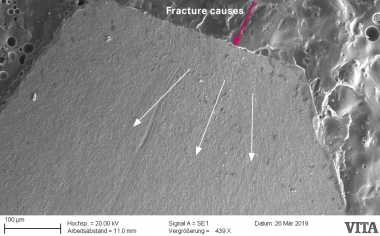
Fig. 1c: Detailed view in the SEM shows the separated portion of the framework as the cause of the fracture.
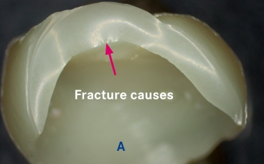
Fig. 2a: Glass ceramic crown fractured following the glaze firing.
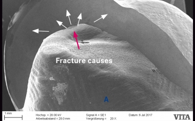
Fig. 2b: A ceramic pin “sintered” with the crown resulted in surface damage when the restoration was removed.
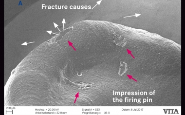
Fig.2c: The detailed view in the SEM shows the impression of the firing pin and the cause of the fracture.